DC Speed Control Module Electrical Machine Trainer Vocational Training Equipment
SR6113E DC Speed Control Module Electrical Machine Trainer Vocational Training Equipment
1 Introduction
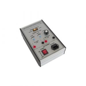
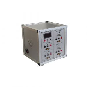
This experimental device can provide excitation voltage and armature voltage for DC motor, and the armature voltage can be adjusted between DC 0 and 220V to realize speed control of DC motor. Through the experiment, and master the principle and control mode, the corresponding knowledge and skills, suits, higher vocational colleges, secondary vocational schools and vocational school related professional teaching and skills training examination.
2 Training Panel Instructions
1. Enable switch
2. Adjustment of soft start time.
3. Excitation voltage output terminal –DC 220V/0.5A.
4. Dual control switch — power switch.
5. Current limit adjustment.
6. Potentiometer — armature voltage adjustment.
7. Armature voltage output terminal –DC 0-220v /4A.
8.Fuse
9. Power socket –AC220V power supply.
3 Operation instruction
1. Carefully check whether there is any safety hazard in the power supply line before power supply. (for example, the copper wire of the insulating layer breaks out and is not allowed to be used)
2. Insert the power cord plug into the AC22V power input socket and power the panel.
3. The test cases on the excitation voltage output terminals using K4 test line is connected to the dc motor excitation winding terminals, the armature voltage output terminals on the test chamber used K4 test line connected to the dc motor armature winding wiring terminals. (dc motor shunt connection mode is adopted here)
4. It will enable the single control button and power double control button to hit OFF state, and the potentiometer will rotate counterclockwise to the minimum. After checking, turn on the power double control button, and the whole device circuit is connected. Turn on the switch and adjust the potentiometer to adjust the speed of the dc motor.Overload Relays Three Pole Teaching Equipment Vocational Educational Equipment
SR6117E Overload Relays Three Pole Teaching Equipment Vocational Educational Equipment For College
1.Working principle and usage
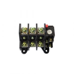
The thermal element of the thermal overload relay is directly or through the current transformer connected to the motor circuit. When the motor is overloaded, the main bimetallic strip is heated to the action temperature, which makes the relay move, and the power circuit of the power failure motor is divided, so that the motor is not damaged by overload. Thermal overload relay action time and the relation of the size of the overload current according to the inverse time, therefore, its thermal characteristic is easy to cooperate with the thermal characteristics of the motor, but also has simple structure, low price, stable performance, convenient use, etc. Therefore, in the 1990s, most squirrel cage rotor motors and partial winding rotor motors still used thermal overload relay as protection of overload, break phase and current imbalance operation. Thermal overload relay can also be used for other electrical equipment to control the heating status of electrical appliances.
2.Technical data
Overload relay (3 – pole 28A & 45A)
Maximum voltage: 600V AC,240VDC.
3.Application range
Thermal overload relay of the scope of application: thermal overload relay for ac 50 hz, rated insulation voltage 660 v, current 0.1 ~ 630 a circuit, it is mainly used for three-phase ac motor overload and phase failure protection. It can also form a starter with an adaptive ac contactor, such as an overview of the diagram thermal relay configuration.
4.Structure and feature
There is a current regulating CAM to adjust the setting current.
There is a temperature compensation device to ensure that the action characteristics are basically unchanged within the ambient temperature range of -20℃ ~ 60℃.
There are reset adjusting knob to adjust the reset mode, manual and automatic two reset state.
There is a stretch spring to make sure the contact action is fast and reliable.
There is a differential phase/three phase unbalance protection device.
The slider/switch position indicator is used to simulate the trip of the thermal relay and display the action status. Through this simulation check and ensure that the auxiliary circuit wiring is correct. When the marking line on the slider is located at the “0” sign, the trip is displayed at the “l” mark.
There is a disconnect button, press the disconnecting button, the normally closed contact opens the serial contactor open circuit, disconnects the load, releases the disconnecting button, and the load is reworked through the contact device.DC Shunt Wound Machine Trainer Electrical Training Equipment Teaching Model
SR6111E DC Shunt Wound Machine Trainer Electrical Training Equipment Teaching Model
1 Introduction
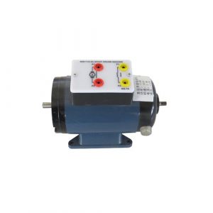
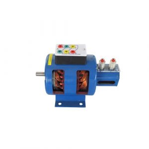
DC compound motor is a DC motor equipped with shunt winding and series winding in the main magnetic pole.
Compound machine excitation winding is divided into two parts, part of the series with the armature winding, the other part with the armature winding in parallel, according to the direction of the magnetic field can be divided into two parts winding generation compound machine and compound machine. Compound DC motor is widely used in ships, trolley buses and lifting mining equipment.
2 Technical data
Rated voltage of compound dc motor :42V.
DC excitation voltage :DC36V;
Rated speed :3000 RPM.DC Motor Compound Excitation Trainer DC Machine Trainer Educational Equipment
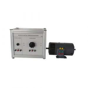
SR6109E DC Motor Compound Excitation Trainer DC Machine Trainer Educational Equipment
1 Introduction
This experimental device can provide DC and AC power supply, and output the protection of fuses, which can provide DC 5V/1.2A, AC 6V/ 1.5A voltage. Configure the moving coil dc 1A and ac 1A pointer table to complete a variety of measurements. Through the experiment, and master the principle and control mode, the corresponding knowledge and skills, suits, higher vocational colleges, secondary vocational schools and vocational school related professional teaching and skills training examination.Three Phases Synchronous Machine Cutaway Models AC Machine Trainer Teaching Model
SR6108E Three Phases Synchronous Machine Cutaway Models AC Machine Trainer Teaching Model
1 Introduction
Synchronous motor is an AC motor with the same rotating speed as the stator rotating field. The rotation speed of the rotor is n=60f/p with the logarithmic p and the power frequency f. The speed n depends on the power frequency f, so the power supply frequency must be constant, the speed is constant, and it has nothing to do with the load. It has the characteristics of high operation stability and overload capacity. It is often used in multi-machine synchronous transmission system, precision speed control system and large equipment.
2 Synchronous machine structure
The structure of synchronous motor is varied, and the rotor structure has hidden pole type and salient pole type. The installation methods include horizontal, suspension, semi-suspension and vertical. The synchronous motor is usually composed of stator, rotor, bearing, baseplate, end cover, collector ring and brush frame, and the motor with the protection grade of IP44 is also included in the cooler. A brief description of the above components is given below:
1. Stator
The stator is composed of a stand, a stator coil and an end collar and supporting part of the stator coil.
1.1 stand
The frame has round stand and square frame (box structure), all welded by steel plate. The motor of the round machine seat of the large horizontal installation, the center of the machine can sink, and the lower part of the seat sometimes sinks to the pit below the installation plane, so the center of the motor is not limited by the outer circle size. Square base are commonly used in protective higher grade of motor, more than the air – air cooling or air – cooled, cooler on the top of the frame, general motors by the center core diameter high limit, lower frame is generally not below the installation plane.
1.2 stator core.
The stator core is composed of a frame and a silicon steel plate in the frame. The core is divided into internal pressure and external pressure mounting: the inner pressure is positioned inside the machine seat, and then the silicon steel sheet is pressed into the seat, and then the tension screw and the pressure ring are pressed and fixed on the machine seat. The outer pressure installation is to make the core frame first, the silicon steel sheet is pressed into the frame, and the embedded wire is then put into the frame by the vacuum pressure immersion treatment.
1.3 stator coil
The stator coil is made of an electromagnetic wire with the corresponding insulation and voltage grade, and the coil can be inserted into the stator core trough through the turns and the coils of the ground resistance test. The linear part of the coil is pressed tightly with the slot wedge. The end part is tightly bound together with the polyester sleeve coil, the end hoop and the supporting part. After the coating is processed, the whole stator becomes a solid whole. The stator coils can be insulated with class B and F, and the special case is H – class insulation. F is used for the above 10KV. Stator coil is the key part of the motor. It is easy to burn the motor due to damage of dirt, moisture and insulation.
The stator lead wire usually has 6 outlet heads and is marked with U1, V1, W1 and U2, V2 and W2. If it is connected with “Y”, then U2, V2 and W2 will be joined together. If it is connected with “delta”, namely, U2-V1, V2-W1, W2-U1, three wiring heads, the high voltage motor is usually connected with Y.
2 Rotor
The rotor of the synchronous motor can be divided into two types: the hidden pole type and the convex one, which are generally made up of magnetic poles, magnetic yoke, rotating shaft and collector ring. 2.1 the magnetic poles are divided into implicit and salient poles. Non-salient pole type magnetic pole is the circumference of a circle is not evenly in rotor slot, made concentric rotor winding coil, embedded in the groove, using metal slot wedge, fixed coil two ends with ring guard banding, the structure of high mechanical strength, good coil heat dissipation, multi-purpose in 1500 turn above the motor. Most of the motors under 1500 RPM are of a convex type magnetic pole.
2.2 the salient pole is composed of magnetic pole, pole coil and pole screw, and the excitation lead is marked as F1 and F2.
2.2.1 pole core is the use of end plate, rod, rivet pole to pole plate riveting pressure into the whole, the pole shoe mount damper bar (starting winding), welding on damping rings on both ends, and notches in playing the punching core at both ends and the damper bar clamping to prevent axial moving, can also be used on the damping of the stretched out on both ends of the core set of brass to fixed
2.2.3 yoke and axis.
Most of the magnetic yoke is made of cast steel, which is also welded with steel plates. The diameter is small, and the magnetic yoke is directly connected with the shaft. The rotating shaft material is generally made of 45 steel and 35 steel, and the special case is made of alloy steel.
2.2.4 rotor assembly:
Yoke thermal set on the rotating shaft first, in the pole core pole wrapping package good insulation, good insulation gasket, set into the pole coil, mount pole bolt, can be installed on the yoke. Note when assembling, insulation gasket can’t more mat, also cannot little cushion, cushion the impact more air gap, less cushion may not tightly on the pole coil. In the case of pole to tighten bolts, general control pole core and the clearance between the yoke within 0.15 mm, at the same time to pay attention to the distance between the poles boots to uniform, the axial location to the end of the pole core level. Spoon fan. Overall varnished, in order to improve the mechanical strength, moisture and heat dissipation performance.
The rotor is the heart of the machine, is made up of many parts assembled, under the effect of electromagnetic force and centrifugal force at high speed, all the parts and fasteners loose easily, cause mechanical accident, therefore, all fastener must be tight when the assembly, and a locking measures, please assemble and maintenance workers should pay attention to check, found that the problem should be handled in a timely manner.Assembly Kit For Transformers Construction Transformer Training Equipment Educational Equipment
SR6105E Assembly Kit For Transformers Construction Transformer Training Equipment Educational Equipment
1.Introduction
The transformer assembly kit is for vocational school, technical institution, college, university students doing assembly and disassembly transformer hand on training. It’s for students to see the inside structure of the transformer, be familar with the function for single phase and three phases transformer in different work power.
1.Technical data
It complete with
Single-phase 200V A transformer
Single-phase 600V A transformer
Single-phase 1000V A transformer
three- phase 300V A transformer
three- phase 600V A transformer
and three- phase 1000V A transformer
English operation/instruction manualAC/DC Power SSR And Relay Driver Board Electrical Training Equipment
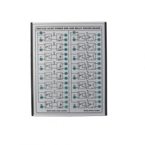
SR6103E AC/DC Power SSR And Relay Driver Board Electrical Training Equipment Educational Equipment
1. Introduction
This experimental device includes two relays: solid-state relays and coil relays, and both have optical decoupling isolation. Through the experiment, and master the principle and control mode, the corresponding knowledge and skills, suits, higher vocational colleges, secondary vocational schools and vocational school related professional teaching and skills training examination.
2.Technical data
providing 8 channels of photo-couple isolated solid state relay modules, plus and additional 8 external relay driver outputs.
3. Operate instructions
1. Carefully check whether there is any safety hazard in the power supply line before power supply. (for example, the copper wire of the insulating layer breaks out and is not allowed to be used)
2. Plug the power cord plug into the laboratory socket to power the device.
3. Use the 2mm safety electrical cable to connect GND with IN, and the relay contact can be moved.ZF-RF3030A RF Training Kit 3.0GHz Technical Educational Teaching Equipment
ZF-RF3030A RF Training Kit 3.0GHz Technical Educational Teaching Equipment. Jinan Should Shine Didactic Equipment Co., Ltd. is company specialized in manufacture and trading Fluid Lab Equipment,air conditioner trainer, refrigeration trainer, Thermal Lab Equipment, Vocational Training Equipment,Didactic Equipment,Engineering Educational Equipment,Technical Teaching Equipment,for university,college,technical institution, polytechnics.Should Shine products has been exported to America,Asia,Europe,Africa, Australia.
AC Circuit Output Module Electronics Trainer Vocational Training Equipment
SR6102E AC Circuit Output Module Electronics Trainer Vocational Training Equipment
1 Introduction
This experimental device can provide ac power supply, the output of circuit breaker and fuse protection, can provide 42V/8A and 380V/1A AC. Configuration of digital voltmeter, voltage commutation switch, digital ammeter, can complete a variety of measurements.
2.Technical data
Power supply; output: protected with thermal relays and fuses: 42V AC., 8A, 3 phase (380V AC) 1 A for mains voltage version). Instruments: 3-digit electronic voltmeter, switchable on the three phases; 3-digits electronic ammeter,
3. Detailed technical data
1. AC380V total power supply —- -4p leakage circuit breaker.
1. AC42V/8A power supply — -2p circuit breaker.
2. Three phase indicator light.
3. Three-phase insurance
4. Three-phase five-wire output terminal.
5. AC42V/8A output terminals and insurance.
6. AC42V/8A output terminals and insurance.
7. AC42V/8A output indicator light.
8. Ac voltmeter –AC500V.
9. Commutation switch
10. Ac ammeter -AC8A.
11. AC500V voltmeter measuring control switch (note: set to the left side, with the use of reversing switch, the internal three-phase power supply can be tested; To the right, use the test line to test the voltage of the external output terminal.
4. Operate instructions
1. Carefully check whether there is any safety hazard in the power supply line before power supply. (for example, the copper wire of the insulating layer breaks out and is forbidden to be used; Whether the terminal screws are loose)
2. Connect the terminals on the power supply wire of the three-phase five-wire system in the laboratory (black, green, red, L1, L2, L3; Blue line zero; Double – color ground wire), power supply to the experimental box.
3. After the check is correct, power the 4P leakage circuit breaker, and the whole device circuit is connected. If you use AC42V/8A power supply, please power the 2P circuit breaker.
4. When measuring voltage, dial the voltage meter to the left and cooperate with the reversing switch to test the internal three-phase power supply and determine whether the phase is missing; To the right, use the test line to test the voltage on the external output terminals and the ac voltage on other devices.Sedimentation Studies Apparatus Fluid Mechanics Lab Equipment Teaching Equipment
SR1120E Sedimentation Studies Apparatus Fluid Mechanics Lab Equipment Teaching Equipment
I.Product overview
1.1 Overview
The equipment is used to study the basic physical process of sedimentation, including the formation of the zone and the hindered precipitation, so that students have a preliminary intuitive understanding of the basic physical process of precipitation. The training of students’ corresponding knowledge and skills is suitable for the practical training and assessment of relevant majors in higher vocational, high school, secondary vocational schools and technical schools.
1.2 Feature
(1) the practical training platform adopts aluminum profile frame structure, each unit is flexible, easy to use and not easy to damage.
(2) five glass columns of the same size are mounted vertically on the back board to form a measurement scale.
(3) each column can be easily removed from the backboard for cleaning, filling and mixing of solid particles.
(4) use the bench base and background light to make the observation more convenient.
1.3 Learning objectives/experiments
determination and comparison of the settling velocities of solids in suspensions
dependent on the solid density and concentration and the liquid density and viscosity
influence of coagulants on the settling velocity1.4 Specification
experiments in the fundamentals of sedimentation
5 transparent tanks with scale for comparison of the settling velocities of solids in various suspensions
tanks removable for filling, mixing and cleaning
tanks backlit by fluorescent tubes to aid observation
3 measuring cups for preparation of suspensions
pycnometer to determine the density of the liquids and solids
stopwatch to record the sedimentation time
recommended accessories: balance,coagulantServo Breaker Driver Trainer Electrical Training Equipment Educational Equipment
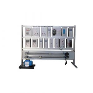
SR1121S Servo Breaker Driver Trainer Electrical Training Equipment Educational Equipment
1 Product Overview
1.1 Profile
The training device includes DC servo drive, AC servo drive and Siemens Sinamics V20 inverter and encoder. Through experiments, students can familiarize themselves with the characteristics of servo brake and drive system, and master the control principle and control mode. To develop students’ technical skills and knowledge suitable for higher vocational education. Higher vocational education, secondary vocational schools and technical schools related to the teaching and skills training assessment.
1.2 Feature
(1) The training platform adopts aluminum profile column frame structure, each unit module is rail-mounted, the module is distinct, easy to use and not easy to damage.
(2) The equipment is complete, the modules are diverse, and can be used in combination to complete the training content of various courses.
(3) The training platform has a good safety protection system.
2 Technical capacity
(1) Input power: three phases five wires AC380V±10% 50Hz
(2) External dimension: 1800 mm×400 mm×1200 mm
(3) Weight: <100kg
(4) Work condition: environment temperature -10℃~+40℃ relative humidity<85%(25℃)
(5)Whole capacity:< 2.0 kva
3 Product consist of
3.1 Power control module
3.2 DC 48V power module
3.3 AC voltage meter
3.4 AC voltage meter
3.5 DC voltage meter
3.6 DC current meter
3.7 Tachometer(2 sets)
3.8 Inverter
3.9 DC driver
3.10 AC Driver
3.11 Limit protect module
3.12 DC servo speed control module
3.13 AC servo speed control module
3.14 DC 24V power module
3.15 Encoder cable
3.16 AC servo control cable
3.17 AC servo motor encoder cable
3.18 AC servo motor power cord
3.19 DC servo Uart cable
3.20 DC servo control signal cable
3.21 DC servo motor power cord
3.22 Three-phase asynchronous motor
4 Experiment that can be finished
4.1 AC servo motor control
4.2 DC servo motor control
4.3 Three phases motor controlDC Output Module Electrical Training Equipment Vocational Educational Equipment
SR6114E DC Output Module Electrical Training Equipment Vocational Educational Equipment
1 Introduction
This experimental device can provide DC power supply, and output the protection of fuses, which can provide DC 42V/3A, DC 220V/1A, DC 0-36v /3A, DC 0-230v /1A. Configure digital voltmeter DC500V to complete a variety of measurements. Through the experiment, and master the principle and control mode, the corresponding knowledge and skills, suits, higher vocational colleges, secondary vocational schools and vocational school related professional teaching and skills training examination.
2 Training panel instruction
1. DC voltage measurement module — -DC 500V.
2. DC voltage module -DC 42V/3A.
3. DC voltage module -DC 220V/1A.
4. Adjustable DC voltage module -DC 0-36v /3A.
5. Adjustable DC voltage module -DC 0-230v /1A.
3.Operation instructions
1. Carefully check whether there is any safety hazard in the power supply line before power supply. (for example, the copper wire of the insulating layer breaks out and is forbidden to be used; Whether the terminal screws are loose)
2. Plug the power cord into the power outlet on the left side of the device, and turn on the power switch after checking. The four dc voltage modules on the front panel can be used at will.
3. When measuring voltage, use the 4mm safety electrical cable to connect to the signal input terminal of the dc voltage measurement module.
- Home
- Products
- Electrical Training Equipment
- Mechatronics Training Equipment
- Refrigeration Training Equipment
- Air Conditioner Trainer
- Fluid Mechanics Teaching Equipment
- Thermal Training Equipment
- Hydraulic Training Workbench
- Pneumatic Training Equipment
- Renewable Training Equipment
- Building Automation Trainer
- Microwave Antenna Trainer
- Vocational Training Equipment
- Food Machine Training Equipment
- PCB Lab Equipment
- About Us
- News
- Contact Us