- Description
- Inquiry
TB230621S43 Digital Circuit Training Kit Teaching Education Equipment for School Lab Electrical Lab Equipment
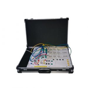
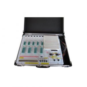
The experimental box is composed of an aluminum-wood alloy box, a high-performance regulated power supply, a common signal source and an experimental circuit area. Among them, the experimental circuit area adopts a fully open mode, and the experimental circuit can be flexibly configured according to the needs to meet the teaching and experimental requirements of students at different levels.
- Main composition
- Working power supply for the experimental circuit: 5V/2A group, ±12V/0.7A group, one fuse for each circuit, each circuit has short-circuit protection and reverse protection circuit, of which +5V power supply has overvoltage protection, undervoltage protection Overvoltage protection and short circuit alarm and automatic shutdown function to ensure the safety of experimental circuit components and personal safety.
- Common signal sources
1) Sequential pulse generating circuit, which provides sequential pulse signals. And there are two groups of positive and negative single-pulse generating circuits, and two groups of positive and single-pulse generating circuits.
2) 10HZ~10KHZ continuously adjustable clock circuit.
3) 1HZ~1MHZ fixed pulse is divided into 16 outputs, 1HZ, 10HZ, 100HZ, 1KHZ, 10KHZ, 100KHZ, 50KHZ, 1000KHZ, 500KHZ, 1MHZ.
4) 16-channel digital input display circuit, with protection function at the input end.
5) 16-way switching value output circuit, the output end has a display circuit, which can directly display the output state of the switching value, and the output end has a protection function.
6) 6-digit seven-segment LED common-cathode digital display with built-in BCD code decoding circuit.
7) 2-bit independent seven-segment LED common cathode digital tube display.
8) 4 sets of BCD code dial switch output circuit, with protection function at the output end.
10) Audio output control circuit with buzzer.
- Test widget
1) One 0-50MHz liquid crystal display frequency meter.
- Experimental circuit area: Independent circuit board design, completely isolated from the experimental signal source, to prevent misoperation during wiring in the experimental circuit area from damaging the main box. The configuration of the experimental circuit area is as follows:
2) Configure an open experimental area, including 6 IC14 round sockets, 6 IC16 round sockets, 4 IC20 round sockets, and 1 IC40 socket (compatible with IC18-IC40, etc.).
2) Provide 1 8Ω speaker, buzzer and 1×2 switch, 4 potentiometers (1k, 50K, 100k, 680K), and multiple resistor and capacitor expansion areas.
3) There are also multiple high-reliability locking anti-rotation stacking sockets (internal connections with integrated block sockets, silver-plated long copper tubes and fixing devices, etc.) as experimental connection points and test points. When experimental wiring, as long as Take the locking plug wire and connect to each other.
- The main board is made of 2mm thick printed circuit board. The graphic symbols of components, components and corresponding wiring are printed on the front, and the printed circuit is printed on the reverse.
- Basic integrated circuits for experiments: 22 pieces such as 74LS00, 74LS02, 74LS04, etc.
- Connection of experimental lines
All signal lead-out jacks adopt Φ2 self-locking gold-coated jacks, which will never oxidize and are beautiful. There are two types of experimental wires: Φ0.5 single-strand copper core wire (compatible with breadboard) and Φ2 self-locking stackable wire.
- Independent module
1) Discrete component module board: the board contains resistors 10Ω, 100Ω, 200Ω, 470Ω, 510Ω, 1K, 1.2K, 1.5K,
4.7K, 5.1K, 10K, 22K, 47K, 100K, 150K, 22M; 20P, 30P, 100 and 100P adjustable, 240P, 300P, 680P, 0.01uF, 0.02uF, 0.047uF, 0.1uF, 10uF/16V, 47uF/16V, 100uF/16V; Diodes 2AK2, 2CK13, 2CK15, IN4007; Transistors 3DG6 and 3DK2; Crystal oscillator 32768HZ; Basic experiment requirements.
- Experimental project
basic experiment
- Transistor switching characteristics, limiter and clamper
- Logic function and parameter test of TTL integrated logic gate
- Logic function and parameter test of CMOS integrated logic gate
- Connection and driving of integrated logic circuits
- Design and test of combinational logic circuits
- Decoder and its application
- Data selector and its application
- Triggers and their application
- Counter and its application
- Shift register and its application
- Pulse distributor and its application
- Using a gate circuit to generate a pulse signal – a self-excited multivibrator
- Monostable trigger and Schmitt trigger – pulse delay and waveform shaping circuit
- Experiment box configuration
| No. | Name | Explanation | quantity |
| 1 | TB230621S43 main box | Including all the contents of the main components such as the chassis, working power supply, common signal sources, and experimental circuit area | 1 set |
| 2 | Power cord | 1.5m | 1 pcs |
| 3 | No. 2 experimental lead | 30cm-50cm | 35 pcs |
| 4 | fuse | 2A | 2 pcs |
| 5 | Experiment Guide | 1 book |
Attached: The use of this experiment box requires supporting instruments: multimeter and oscilloscope.


-300x300.jpg)
-300x300.jpg)
