
- Description
- Inquiry
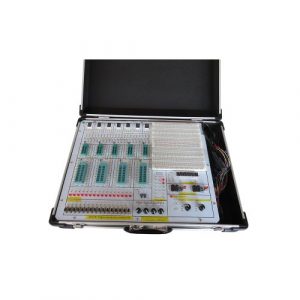
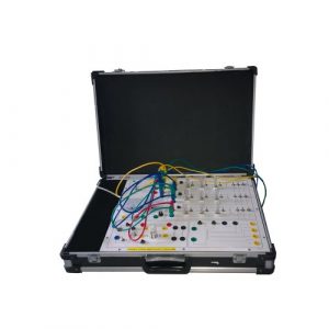
TB230621S01 High Frequency Electronic Circuit Training Kit Educational Equipment Electrical Laboratory Equipment
Product description
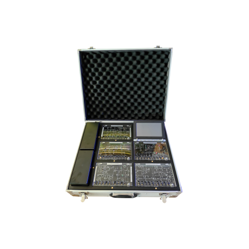
The whole system consists of one main control module and five basic experimental modules, which can complete more than 20 practical training including high-frequency electronic each
unit circuit experiment, wireless transceiver system debugging, fault setting determination, and experimental evaluation. Product compositions
Baseboard module:
| Low frequency DDS signal source
| Function signal | Frequency adjustable from 0.1 to 50KHZ, 10MVp-p to 5Vp-p (continuously adjustable) |
| Music signal | Programmable | |
| Modulation signal | The modulation signal and carrier synchronization can display the AM, DSB and FM waveforms on the common oscilloscopes | |
| Telephone interface | Wireless voice communication can be carried out | |
| Audio amplifier, speaker
| Perform power amplifier output on the receiver’s audio signal | |
| DDS high frequency signal source
| High frequency sine wave
| Frequency range: 1HZ ~ 25MHZ, output amplitude: 100MVp-p to 2Vp-p (continuous adjustable)
|
| Frequency meter
| Measurement frequency range: 0-25MHZ, input voltage not less than 50mv;
| |
| Frequency sweep meter
| Amplitude and frequency characteristics of color LCD display, sweep frequency range, time programmable
|
Experiment module
| Sine wave oscillator and transistor mixing
| LC frequency 4-12MHz, can be used to study the amplitude frequency characteristics of the Schiller oscillation circuit and the Clapper oscillation circuit. Crystal: 8.8MHZ. Triode mixer circuit: Local oscillator input 8.8MHZ carrier 6.3MHZ, output 2.5MHZ. Can be completed: Operation point setting, voltage impact on the oscillation frequency, oscillation frequency, high frequency signal amplitude, filter center frequency and other control assessment.
|
| Intermediate release AGC and demodulation module
| Amplify the 2.5MHz intermediate frequency signal, and the gain is greater than 20db. Envelope detection, observe the diagonal cutting distortion and bottom cutting distortion, and low frequency amplification. Can be completed: Intermediate frequency selection loop, Intermediate release gain, detection distortion, signal output amplitude and other parameters control and assessment. |
| Resonant circuit module | Single tuning, double tuning, through the varactor to adjust the tuning loop parameters, reliable and stable performance; center frequency 6.3MHZ. Can be completed: Single tuning double tuning loop parameters, tuning loop frequency-selective characteristics control and assessment.
|
| High frequency power amplifier module
| Wireless transmission: 6.3MHZ transmit for base amplitude modulation. Observe the phenomenon of class-C working state of high-frequency power amplifiers, test the tuning characteristics and load characteristics of class-C amplifiers, test the effects of changes in excitation signals, load changes and power supply voltage variations on the operating state, and the cosine pulse waveform can be clearly observed in three states of undervoltage, critical and overvoltage. Amplitude modulation: Can be completed: Power amplifier work status control and assessment.
|
| Frequency modulation and capacitance coupling frequency discrimination module
| Capacitive coupling loop phase discriminator, slope discriminator 6.3MHZ center frequency. Synchronous demodulation and integrated mixing (Local oscillator input 8.8MHZ carrier 6.3MHZ, output 2.5MHZ). Can be completed: FM signal center frequency, signal amplitude, frequency discrimination loop characteristics, operating point parameter control and assessment.
|
| Integrated multiplier amplitude modulation, mixing and synchronous demodulation modules
| AM, DSB, SSB modulation and demodulation, carrier frequency 100KHZ-2.5MHZ. Can be completed: Modulation, modulation signal output, mixing filter and other functional assessment.
|
Technical parameters
- The system has built-in DDS low frequency signal source (AM, DSB, FM waveform for
function signal, music signal, modulation signal and carrier signal synchronization), microphone signal, DDS high frequency signal source and frequency meter. 1) Low frequency function signal:
Frequency: 100HZ-200KHZ
Amplitude: 0-5Vpp
2) High frequency signal source:
Frequency: 100KHZ-40MHZ
Amplitude: 50mv-2000mvpp
3) Frequency meter:
Frequency range: 0-40MHZ
Amplitude: not less than 50mv
- Sweeper
The system has a built-in sweep signal source and amplitude phase detection circuit, which
can directly display the amplitude and frequency characteristics of the resonant circuit on
the LCD screen. 1) Sweep range: 1MHZ-20MHZ adjustable home, start and stop frequency can be set
2) Sweep time: Programmable
3) Frequency standard instructions: Direct reading bandwidth and resonant peak frequency of mobile frequency standard
Basic experiments
- Small-signal tuning amplifier circuit experiment (including single-tuning and double-tuning)
- Nonlinear Class C Power Amplifier Circuit Experiment
- Three-point oscillator experiment (including LC oscillator and crystal oscillator)
- Intermediate frequency amplifier experiment
- Mixer experiment (including transistor mixing and diode ring mixer)
- Envelope detection and synchronous detection experiments
- Variable capacitance diode frequency modulation experiment
- Discriminator experiment (capacitance couple loop phase discriminator, slope discriminator)
- AM Transmitter Joint Experiment
- AM Receiver Joint Test Experiment
- Transmit and receive complete systems of the intermodulation experiment
- FM transmitter test experiment
- FM receiver joint experiment
Related Products
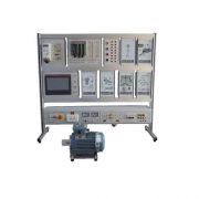
ZE1121 Air Conditioning Electrical Control Board Trainer
ZE1121 Air Conditioning Electrical Control Board Trainer. Jinan Should Shine Didactic Equipment Co., Ltd. is company specialized in manufacture and trading Engineering Educational Equipment,Technical Teaching Equipment, Vocational Training Equipment, Didactic Equipment for university,college, technical institution, polytechnics.Should Shine products has been exported to America,Asia,Europe, Africa, Australia.
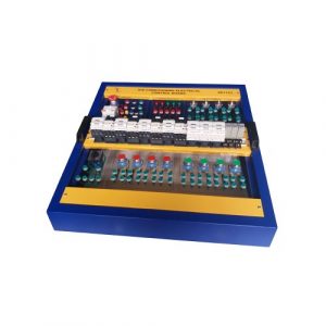
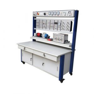
SR2112S Power Electronics Trainer Didactic Equipment
Power Electronics Trainer Didactic Equipment for college,university,technical institute,vocational schools.
ZE1113 Electrician Experiment Box Engineering Educational Equipment
ZE1113 Electrician Experiment Box Engineering Educational Equipment. Jinan Should Shine Didactic Equipment Co., Ltd. is company specialized in manufacture and trading Engineering Educational Equipment,Technical Teaching Equipment, Vocational Training Equipment, Didactic Equipment for university,college, technical institution, polytechnics.Should Shine products has been exported to America,Asia,Europe, Africa, Australia.
ZE1109 Electronics Educational Equipment Teaching Equipment
ZE1109 Electronics Educational Equipment Teaching Equipment Jinan Should Shine Didactic Equipment Co., Ltd. is company specialized in manufacture and trading Engineering Educational Equipment,Technical Teaching Equipment, Vocational Training Equipment, Didactic Equipment for university,college, technical institution, polytechnics.Should Shine products has been exported to America,Asia,Europe, Africa, Australia.
ZE1111 Didactic Equipment
ZE1111 European Type Electronics Workbench Didactic Equipment. Jinan Should Shine Didactic Equipment Co., Ltd. is company specialized in manufacture and trading Engineering Educational Equipment,Technical Teaching Equipment, Vocational Training Equipment, Didactic Equipment for university,college, technical institution, polytechnics.Should Shine products has been exported to America,Asia,Europe, Africa, Australia.
ZE1110 Teaching Equipment Digital Electronics Trainer
ZE1110 Teaching Equipment Digital Electronics Trainer
Jinan Should Shine Didactic Equipment Co., Ltd. is company specialized in manufacture and trading Engineering Educational Equipment,Technical Teaching Equipment, Vocational Training Equipment, Didactic Equipment for university,college, technical institution, polytechnics.Should Shine products has been exported to America,Asia,Europe, Africa, Australia.
ZE3161 Digital Educational Kit Vocational Training Equipment
ZE3161 Digital Educational Kit Vocational Training Equipment for university,college,technical schools,technical institute, vocational training schools.
ZE1108 Technical Teaching Equipment Electronics Workbench
ZE1108 Technical Teaching Equipment Electronics Workbench. Jinan Should Shine Didactic Equipment Co., Ltd. is company specialized in manufacture and trading Engineering Educational Equipment,Technical Teaching Equipment, Vocational Training Equipment, Didactic Equipment for university,college, technical institution, polytechnics.Should Shine products has been exported to America,Asia,Europe, Africa, Australia.
ZE3198 PLC Training Simulator Educational Equipment
ZE3198 PLC Training Simulator Educational Equipment for college,university, technical institute,vocational training schools.
ZE1105 Electronics Workbench Educational Training Equipment
ZE1105 Electronics Workbench Educational Training Equipment
Jinan Should Shine Didactic Equipment Co., Ltd. is company specialized in manufacture and trading Engineering Educational Equipment,Technical Teaching Equipment, Vocational Training Equipment, Didactic Equipment for university,college, technical institution, polytechnics.Should Shine products has been exported to America,Asia,Europe, Africa, Australia.
-300x300.jpg)