- Description
- Inquiry
SSR20240409B01 Pressure control unit Technical Training Equipment
Description
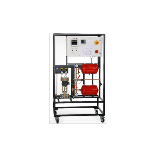
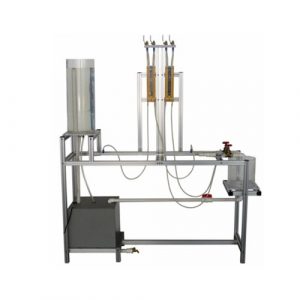
This trainer provides a comprehensive experimental introduction to the fundamentals of control engineering using an example of pressure control.
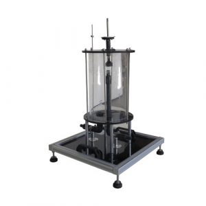
The air pressure control system is a 2nd order system. It comprises two in-line pressure tanks interconnected by a flow control valve. An additional valve on the second tank makes air tapping possible and so can be used to simulate a disturbance variable. A pressure sensor measures the pressure in the second vessel. The controller used is a state-of-the-art digital industrial controller. The actuator in the loop is a pneumatically operated control valve with a standardised current signal input. The controlled variable X and the manipulating variable Y are plotted directly on an integrated 2-channel line recorder. Alternatively, the variables can be tapped as analogue signals at lab jacks on the switch cabinet. This enables external recording equipment, such as an oscilloscope or a flatbed plotter, to be connected.
FEATURES
Specification
[1] trainer for control engineering experiments
[2] pressure control process, equipped with standard industrial components
[3] pressure measurement by pressure sensor
[4] generation of disturbance variables by drain valve
[5] 2 pressure tanks with pressure relief valve and manometer for direct observation of the tank pressure
[6] valves permit investigation of a 1st order controlled system (1 tank) or 2nd order controlled system (2 in-line tanks)
[7] pneumatically operated control valve with electro-pneumatic positioner
[8] digital controller, parameterisable as a P, PI or PID controller
[9] 2-channel line recorder
[10] process variables X and Y accessible as analogue signals via lab jacks
Technical Data
2 pressure tanks
– capacity: each 10L
– max. pressure: 10bar
– operating pressure: 6bar
Pressure sensor: 0…6bar
Pneumatically operated control valve
– connecting flanges: DN15
– Kvs: 0,1m³/h
– reference variable: 4…20mA
– stroke: 15mm
– characteristic curve equal-percentage
Line recorder
– 2x 4…20mA
– feed rate 0…7200mm/h, stepped
Controller
– process variables X, Y as analogue signals: 4…20mA
1 Pressure controlled by proportionally varying pump speed (Inflow Control)
2 Pressure controlled by time-proportionally opening of a solenoid valve (Outflow Control)
3 * Direct control or Indirect control using an external controller:
* PID Controller
* PLC Controller
Related Products
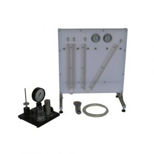
ZM7107 Pressure Measurement Pressure Gauges Teaching Equipment
ZM7107 Pressure Measurement Pressure Gauges Teaching Equipment. Jinan Should Shine Didactic Equipment Co., Ltd. is company specialized in manufacture and trading Vocational Training Equipment,Didactic Equipment,Engineering Educational Equipment,Technical Teaching Equipment,for university,college,technical institution, polytechnics.Should Shine products has been exported to America,Asia,Europe,Africa, Australia.
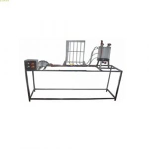
ZM7111A Bernoulli’s Principle Demonstration Apparatus Teaching Equipment
ZM7111A Bernoulli’s Principle Demonstration Apparatus Teaching Equipment. Jinan Should Shine Didactic Equipment Co., Ltd. is company specialized in manufacture and trading Vocational Training Equipment,Didactic Equipment,Engineering Educational Equipment,Technical Teaching Equipment,for university,college,technical institution, polytechnics.Should Shine products has been exported to America,Asia,Europe,Africa, Australia.
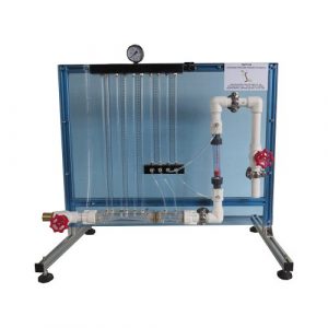
ZM7104 Venturimeter,Orifice plate,Rotameter Flow Measure Teaching Equipment
ZM7104 Venturimeter,Orifice plate,Rotameter Flow Measure Teaching Equipment. Jinan Should Shine Didactic Equipment Co., Ltd. is company specialized in manufacture and trading Vocational Training Equipment,Didactic Equipment,Engineering Educational Equipment,Technical Teaching Equipment,for university,college,technical institution, polytechnics.Should Shine products has been exported to America,Asia,Europe,Africa, Australia.
ZM7109 Hydrostatic Pressure in Liquids Educational Equipment
ZM7109 Hydrostatic Pressure in Liquids Educational Equipment. Jinan Should Shine Didactic Equipment Co., Ltd. is company specialized in manufacture and trading Vocational Training Equipment,Didactic Equipment,Engineering Educational Equipment,Technical Teaching Equipment,for university,college,technical institution, polytechnics.Should Shine products has been exported to America,Asia,Europe,Africa, Australia.
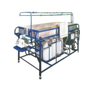
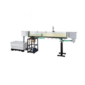
SR-S12 Advanced Hydrology Study System Teaching Equipment
SR-S12 Advanced Hydrology Study System Teaching Equipment. Jinan Should Shine Didactic Equipment Co., Ltd. is company specialized in manufacture and trading Vocational Training Equipment,Didactic Equipment,Engineering Educational Equipment,Technical Teaching Equipment,for university,college,technical institution, polytechnics.Should Shine products has been exported to America,Asia,Europe,Africa, Australia.
ZM7103 Hydraulics Bench with Pump Educational Equipment
ZM7103 Hydraulics Bench with Pump Educational Equipment. Jinan Should Shine Didactic Equipment Co., Ltd. is company specialized in manufacture and trading Vocational Training Equipment,Didactic Equipment,Engineering Educational Equipment,Technical Teaching Equipment,for university,college,technical institution, polytechnics.Should Shine products has been exported to America,Asia,Europe,Africa, Australia.
ZM2142 Pipes Fluid Friction Venturi Method Hydraulic Bench Teaching Equipment
ZM2142 Pipes Fluid Friction Venturi Method Hydraulic Bench. Jinan Should Shine Didactic Equipment Co., Ltd. is company specialized in manufacture and trading Vocational Training Equipment,Didactic Equipment,Engineering Educational Equipment,Technical Teaching Equipment,for university,college,technical institution, polytechnics.Should Shine products has been exported to America,Asia,Europe,Africa, Australia.
ZM7110B Osborne Reynolds Trainer Teaching Equipment
ZM7110B Osborne Reynolds Trainer Teaching Equipment. Jinan Should Shine Didactic Equipment Co., Ltd. is company specialized in manufacture and trading Vocational Training Equipment,Didactic Equipment,Engineering Educational Equipment,Technical Teaching Equipment,for university,college,technical institution, polytechnics.Should Shine products has been exported to America,Asia,Europe,Africa, Australia.
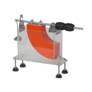
ZM7112 Measurement of Jet Forces Technical Teaching Equipment
ZM7112 Measurement of Jet Forces Technical Teaching Equipment. Jinan Should Shine Didactic Equipment Co., Ltd. is company specialized in manufacture and trading Vocational Training Equipment,Didactic Equipment,Engineering Educational Equipment,Technical Teaching Equipment,for university,college,technical institution, polytechnics.Should Shine products has been exported to America,Asia,Europe,Africa, Australia.
ZM7105 Over Weirs Flow Measuring Teaching Equipment
ZM7105 Over Weirs Flow Measuring Teaching Equipment. Jinan Should Shine Didactic Equipment Co., Ltd. is company specialized in manufacture and trading Vocational Training Equipment,Didactic Equipment,Engineering Educational Equipment,Technical Teaching Equipment,for university,college,technical institution, polytechnics.Should Shine products has been exported to America,Asia,Europe,Africa, Australia.
-300x300.jpg)