Pneumatic Training Equipment Vocational Training Equipment Educational Equipment
ZMP2102 Pneumatic Training Equipment Vocational Training Equipment Educational Equipment
1. Introduction
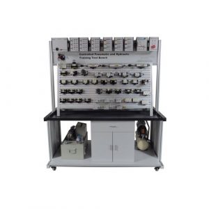
Electro pneumatic trainer is designed for “hydraulic and pneumatic training”, it meets modern pneumatic transmission requirement. Students can learn basic pneumatic circuit control knowledge, and practice hand on ability. Pneumatic trainer combines electrical and mechanical transmission knowledge.
This trainer is suitable for colleges, engineer university, technical schools, vocational schools, engineer training centers, factory training department etc.
Through this trainer, students can master pneumatic components structure, pneumatic circuit control theory, pneumatic circuit design, and hand on ability for pneumatic trainer.
This trainer is flexible and students can design their own pneumatic circuit.
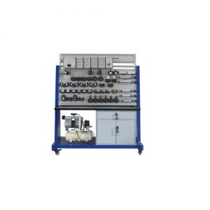
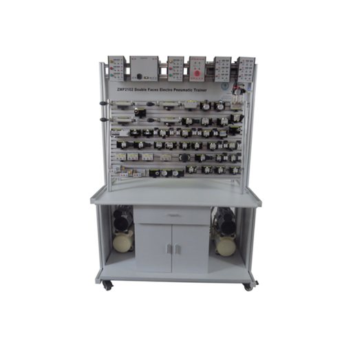
II. Basic structure
Pneumatic control experiment workbench including experiment workbench, experiment shelf, pneumatic components etc.
Pneumatic components and real equipment: air filter, decrease pressure valve, service unit, hand-operated direction valve, pneumatic control direction valve, strike valve, check valve, throttle valve, exhaust valve, single acting cylinder, double acting cylinder etc.
All PLC program software is teaching edition=crack edition=free edition.
A. Improvement on trainees’ familiarization of the principles and applications of various air pressure components.
B. Demonstration of air-pressure loop design.
C. Training of PLC programming,
including architecture, instructions and ladder diagram. *
(2) Pneumatic Workbench
A. It is designed to be flexible to satisfy individual’s needs.
B. A complete workbench mainly consists of 3 parts :
(a) Electro-Modules Frame
(b) Working Board (double side)
(c) Working Table (single or double side)
C. The combinations of the workbench can be modified based on different lab requirement.
D. A complete workbench allows customers to carry out all listed pneumatic experiments. In PART I and PART II, pneumatic components are powered by
Air Supply Unit and operated on Working Board area through connected Air Hose.
E. In PART III, the electrical components mounted on Electro-Modules Frame are linked to the pneumatic system through Connecting Lead and powered by Air Supply Unit.
F. End user are also welcome to adopt Programmable Logic Controller (PLC) for
implementation of PART III. That means Programmable Logic Controller Trainer is an alternative to Electro-Modules Frame and a corresponding electrical device.
(3) Electro-Modules Frame (Excluding Electrical Components)
A. A cabinet frame is available for mounting electrical components on either side.
B. This steel frame can accommodate up to 15 electro-modules at least.
C. Size: minimum 1260 mm(W) x 250 mm(D) x 360 mm(H) ±10%
(4) Working Board
A. Double-side aluminum grooved panel – minimum 1260 x 750 mm
B. A working surface up to 1200 x 700 mm
(5) Working Table
A. Single-side worktable in size minimum 1300 mm(W) x 700 mm(D) x 850mm(H)±10% Drawer units in steel with one flat drawer and four large
drawers that can be loaded up to 20 kg per drawer.
B. Double-side worktable with minimum 1300 mm(W) x 800 mm(D) x 850mm(H)±10%
Two drawer units in steel with one flat drawer and four large drawers that can be loaded up to 20 kg per drawer. •
C. The drawers with different rollers that feature an easy-gliding system for smooth running and
Additional breaking.
(6) Reed Switch
A. Operating voltage : minimum 24 VDC
B. Max. current: 100 mA
C. Frequency range: 3 – 250 Hz
(7) Connecting Lead Holder
A. Mobile type, with 5-foot tubular and 5 casters
B. Height: minimum 1400 mm, iron plate suitable
C. with minimum 20 connecting leads slots
(8) Pneumatic Components
A. Air Service Unit
(a) Filter-Regulator-Lubricator (FRL) assembly
(b) Adjustable pressure: 0 – 9.9 kg/cm2
(c) Sliding exhaust valve mounted
(d) Filtration: minimum 40pm
B. Pressure Gauge
(a) Operating pressure: 0 -10 kg/cm2
(b) Gauge size: minimum 1.5 inch.
C. Air Manifold
(a) Check connector for 04 plastic tubing 6ea Connector size : 1/4 inch
(b) Operating pressure: minimum 0-12 kg/cm2
D. Single-Acting Air Cylinder
(a) Cylinder internal diameter: minimum 32mm Stroke length : minimum 150 mm
(b) Operating pressure: 1.6 – 9..0 kg/cm2
E. Double-Acting Air Cylinder
(a) Cylinder internal diameter: minimum 32mm Stroke length : minimum 150 mm
(b) Operating pressure: 0.4 – 9.0 kg/cm2
(c) Air cushion
F. 3/2-Way Directional Control Valve
(a) Single air operated, spring return
(b) NC type
(c) Flow rate: minimum 200 l/min
(d) Operating pressure: 1.5 – 8.0 kg/cm2
(e) Max, pressure: 10.5 kg/cm2
G. 5/2-Way Directional Control Valve
(a) Single air operated, spring return
(b) Flow rate: 200 l/min
(c) Operating pressure: 1.5 – 8.0 kg/cm2
(d) Max. Pressure: 10.5 kg/cm2
H. 5/2-Way Directional Control Valve
(a) Double air operated, air return
(b) Flow rate: minimum 200 l/min
(c) Operating pressure: 1.5 – 8.0 kg/cm2
(d) Max. Pressure: 10.5 kg/cm2
I. 5/2-Way Single-Solenoid Valve
(a) Solenoid voltage: minimum 24 VDC
(b) Single solenoid operated, spring return, with LED
(c) Operating pressure: 1.5 – 8.0 kg/cm2
(d) Max. Pressure: 10 kg/cm2
J. 5/2-Way Double-Solenoid Valve
(a) Solenoid voltage: minimum 24 VDC
(b) Double solenoid operated, with LED Operating pressure: 1.5 – 8.0 kg/cm2
(c) Max. Pressure: 10 kg/cm2
K. 3/2-Way Pushbutton Valve
(a) Spring return, flat type, NC type
(b) Operating pressure: 0 – 8 kg/cm2
(c) Max. Pressure: 10 kg/cm2
L. 3/2-Way Manual Valve
(a) Spring return, 2-position selector
(b) Operating pressure: 0 – 8 kg/cm2
(c) Max. Pressure: 10 kg/cm2
M. 3/2-Way Manual Valve
(a) Spring return, push & lock NO type
(b) Operating pressure: 0 – 8 kg/cm2
(c) Max. Pressure: 10 kg/cm2
N. 5/2-Way Pushbutton Valve
(a) Spring return, flat type
(b) Operating pressure: 1.5 – 8.5 kg/cm2
(c) Max. Pressure: 10 kg/cm2
O. 3/2-Way Roller Valve
(a) Unidirectional
(b) Operating pressure: 0 – 8 kg/cm2
(c) Max’ pressure: 10 kg/cm2
P. 3/2-Way Roller Valve
(a) Bi-directional
(b) Operating pressure: 0 – 8 kg/cm2
(c) Max. Pressure: 10 kg/cm2
Q. OR Valve (Shuttle)
(a) OR logic
(b) Operating pressure: 0.2 – 9.9 kg/cm2
R. AND Valve (Dual-Pressure)
(a) AND logic
(b) Operating pressure: 0.2 – 9.9 kg/cm2
S. Quick-Exhaust Valve
(a) Pilot type,
T. One-Way Flow-Control Valve
(a) Adjust: 10-turn, with speed controller
U. Sequence Valve
(a) Operating pressure: 1.5-8 kg/cm2
V. Time Delay Valve
(a) Operating pressure: 2 – 8 kg/cm2
(b) Time delay: 0.1 – 30 sec
(c) Min. reset time <0.1 sec
W. Pressure Switch
(a) Operating pressure: 1.5 kg/cm2
(b) Max. Voltage/current: 250 VDC/0.25A
(c) 125 VDC/0.5A
X. Air Hose
(a) Inner / outer diameter: 2 mm/4 mm Length : 25 M
Y. Connecting Lead
(a) Lead diameter: minimum 4 mm, Length :0.25M, 0.5M.1M
(b) Color: red, yellow, blue etc. 1 set: 60 pcs or above
Z. Limit Switch
(a) Roller lever type
(b) Contacts: NO, NC.
AA. 3-Way Distributor
(a) Connector for 04 plastic tubing 6ea
(b) Connector size: % inch.
(9) Electrical Components
A. DC Power Supply
(a) Input voltage : 100 – 240VAC/1.7 A Output voltage : minimum 24 VDC/4.2 A
(b) Terminal: 2 sets for 土 DC output with power I/O indicator
(c) 2 terminal sets for power output
B. Pushbutton Switch
(a) Spring return
(b) Pushbutton switch with illuminated indicator
(c) Including NC, NO contacts
(d) Operation voltage: minimum 24 VDC
(e) Max. current: 3 A
C. Relay
(a) 4 sets of NC, NO, COM contacts
(b) With LED indicator
(c) Operation voltage: minimum 24 VDC
(d) Max. Current: 5 A
D. Timing Relay
(a) ON-Delay type
(b) Operation voltage minimum 24 VDC
(c) Max. Current: 5 A
(d) Time delay: 0.05sec – 300 hour multi switch
(e) 2 sets of NC, NO, COM contacts
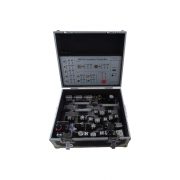
(f) With LED indicator Programmable Logic Controller Trainer
(1) Functions:
A. Input-simulation switches function as level and pulse Input for different input signal
B. It is particularly suitable for installation of output relay helps to increase load current
C. Easy-to-use, Windows-based development software
D. Assorted peripheral devices and other devices that support external extensions, it particularly suits
Laboratory experiment and project implementation.
E. Various simulations I/O devices for studying and observing the results
F. Using 4mm safety sockets on Input / Output terminals to ensure users’ safety
G. The suitcase-design makes it easy to carry, move and store
(2) AC adapter: Input AC 100〜240V, Output DC 24V
(3) PLC main unit: SIEMENS SIMATIC S7-224 or others
(4) Digital input: 14
(5) Digital output: 10
(6) Support high-speed counters : 6 (total)
(7) Support timers : 256 total timers; 4 timers(1 ms); 16 timers(10ms); 236 timers(100ms)
(8) Communication ports : RS-485 or USB
(9) Module expansion port and DIO extension port
(10) Traffic light control module
(11) Tank-filling device module
(12) 4-digit 7-segment display
(13) 4-digit thumbwheel switch
(14) Step motor
(15) Encoder
(16) 24V DC motor
(17) Proximity sensor
(18) Micro switch
(19) Buzzer
(20) 4×4 keypad
(21) 24V DC expansion power
(22) Windows-based programming software (STEP 7- Micro/ WIN) allows the user to modify the program while running it.
(23) System Requirements
A. PC with Pentium It or better CPU
B. Windows 98 / 2000 / XP / Vista / 7
C. USB / PPI Multi-Master Cable
D. STEP 7- Micro/WIN software CD
(24) Accessories
A. Power Cord
B. Experiment Manual
C. Connecting Leads Set
- Description
- Inquiry
ZMP2102 Pneumatic Training Equipment Vocational Training Equipment Educational Equipment
1. Introduction
Electro pneumatic trainer is designed for “hydraulic and pneumatic training”, it meets modern pneumatic transmission requirement. Students can learn basic pneumatic circuit control knowledge, and practice hand on ability. Pneumatic trainer combines electrical and mechanical transmission knowledge.
This trainer is suitable for colleges, engineer university, technical schools, vocational schools, engineer training centers, factory training department etc.
Related Products
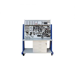
Training Bench for Proportional Pneumatic Circuits Vocational Training Equipment Pneumatic Training Equipment
ZMP1109 Training Bench for Proportional Pneumatic Circuits Vocational Training Equipment Pneumatic Training Equipment for college, vocational training center, university.
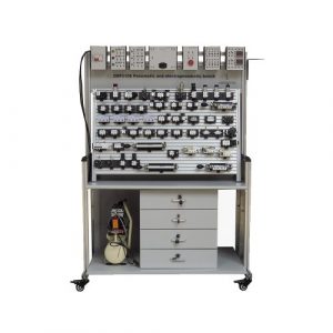
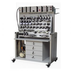
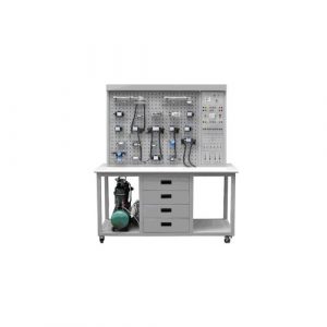
ZMP2106 Double Side Electro Pneumatic Training Workbench Teaching Equipment
ZMP2106 Double Side Electro Pneumatic Training Workbench Teaching Equipment for college, university.
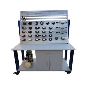
ZMP1102 Basic Pneumatic Training Workbench Educational Equipment
ZMP1102 Basic Pneumatic Training Workbench Educational Equipment. Jinan Should Shine Didactic Equipment Co., Ltd. is company specialized in manufacture and trading Engineering Educational Equipment,Technical Teaching Equipment,Vocational Training Equipment,Didactic Equipment for university,college,technical institution, polytechnics.Should Shine products has been exported to America,Asia,Europe,Africa, Australia.
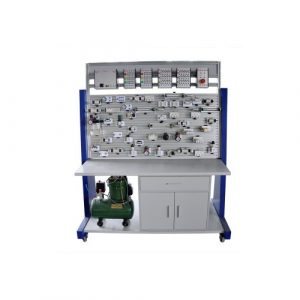
ZMP1103 Electro Pneumatic Training Workbench Teaching Equipment
ZMP1103 Electro Pneumatic Training Workbench Teaching Equipment. Jinan Should Shine Didactic Equipment Co., Ltd. is company specialized in manufacture and trading Engineering Educational Equipment,Technical Teaching Equipment,Vocational Training Equipment,Didactic Equipment for university,college,technical institution, polytechnics.Should Shine products has been exported to America,Asia,Europe,Africa, Australia.
ZMH2105 Electro Pneumatic Trainer Hydraulic Didactic Equipment
ZMH2105 Electro Pneumatic Trainer Hydraulic Didactic Equipment
System introduction
This system is basic electro pneumatic control circuit, supply advanced training frame.
This trainer is to solve electro pneumatic control ., and supply training for electro pneumatic control in technical aspect. At the same time, introduce electro pneumatic, and electro pneumatic components function and application.
This equipment build basic and electro pneumatic control circuit .
Aluminum base panel, with a parallel T slot, components can be
disassembly
I. Introduction
Electro pneumatic trainer is designed for “hydraulic and pneumatic training”, it meets modern pneumatic transmission requirement. Students can learn basic pneumatic circuit control knowledge, and practice hand on ability. Pneumatic trainer combines electrical and mechanical transmission knowledge.
This trainer is suitable for colleges, engineer university, technical schools, vocational schools, engineer training centers, factory training department etc.
Through this trainer, students can master pneumatic components structure, pneumatic circuit control theory, pneumatic circuit design, and hand on ability for pneumatic trainer.
This trainer is flexible and students can design their own pneumatic circuit.
II. Basic structure
Pneumatic control experiment workbench including experiment workbench, experiment shelf, pneumatic components etc.
Pneumatic components and real equipment: air filter, decrease pressure valve, service unit, hand-operated direction valve, pneumatic control direction valve, strike valve, check valve, throttle valve, exhaust valve, single acting cylinder, double acting cylinder etc.ZMP2103 Double Face Pneumatic Trainer Didactic Equipment
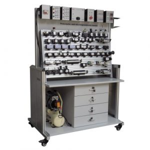
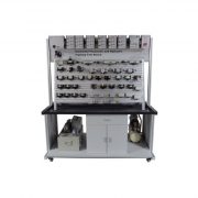
ZMP2103 Double Face Pneumatic Trainer Didactic Equipment
Pneumatic Technology Trainer Double Face
• This device is composed of control unit, high quality pneumatic components, pollution dealing unit, filter unit, specific lubrication unit, pressure measurement unit, air compressor unit, aluminium alloy mounting panel (double face), different type pneumatic joints, tool kits, pneumatic simulation software and so on. It can be used for various pneumatic transmission demonstrations, pneumatic transmission circuit training, which covers the objects of pressure, speed control, direction control and so on. By the operation of this device, students can understand the structure and function of various pneumatic components and circuit, the working principle of air source part, the assembly and disassembly of each component and so on.
EXPERIMENTS
• Understanding of pneumatic components structure, symbols and functions
• Reversing loop of push valve controlled single cylinder
• Speed control loop of single cylinder
• Manual controlled reversing loop of direction valve
• Pneumatic controlled reversing loop of direction valve
• Speed control loop of double cylinder
• Speed control loop of throttle valve
• Sequential loop of two cylinder
• Reversing loop of gate valve controlled single cylinder
• Remote controlled decompression loop
• Push valve controlled double cylinder loop
• Relief valve controlled relief loop
• Two hands controlled single cylinder reversing loop
• Disassembly and assembly of direction valve
• Disassembly and assembly of double valve
• Disassembly and assembly of one way valve
• Disassembly and assembly of roller valve
• Disassembly and assembly of relief valve
• Disassembly and assembly of push valve
• Disassembly and assembly of gate valveZMP2104 PLC Electric Pneumatic Training Workbench Double Sides
ZMP2104 PLC Electric Pneumatic Training Workbench Double Sides. Jinan Should Shine Didactic Equipment Co., Ltd. is company specialized in manufacture and trading Engineering Educational Equipment,Technical Teaching Equipment,Vocational Training Equipment,Didactic Equipment for university,college,technical institution, polytechnics.Should Shine products has been exported to America,Asia,Europe,Africa, Australia.
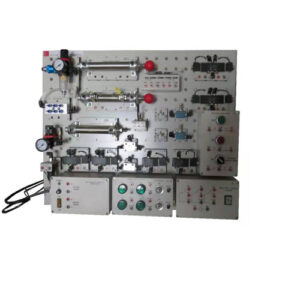
Electro Pneumatic Trainer Panel Type Vocational Training Equipment Pneumatic Training Equipment
ZMP1105 Electro Pneumatic Trainer Panel Type Vocational Training Equipment Pneumatic Training Equipment for college, vocational training center, university.
Pneumatic Training Workbench Vocational Training Equipment Pneumatic Workbench
ZMP1100 Pneumatic Training Workbench Vocational Training Equipment Pneumatic Workbench for college, vocational training center, university.
Transparent Pneumatic Training Workbench Vocational Training Equipment Pneumatic Bench
ZMP1101 Transparent Pneumatic training workbench vocational training equipment pneumatic bench for college, vocational training center, university.