- Description
- Inquiry
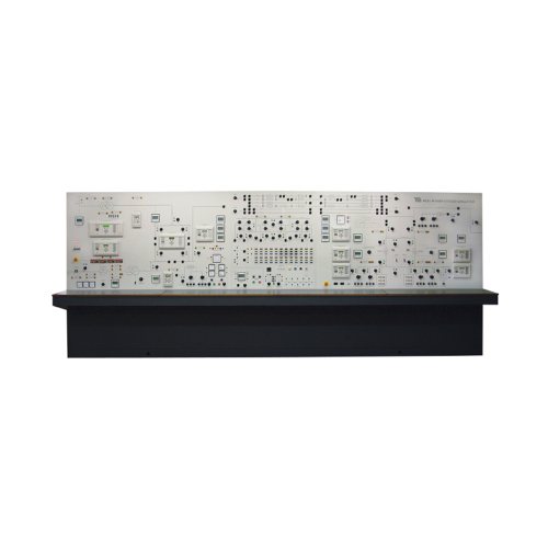
ZE8552 Power System Trainer school teaching equipment Electrical Skills Training
Power System Trainer (PSS1): A self-contained unit that simulates all parts of electrical power systems and their protection, from generation to utilization
Key Features
Simulates generation, transmission, transformation, distribution, utilization and protection in one self-contained unit
Includes prime mover and generator to simulate power generation
Twin distribution transformers for parallel transformer and load flow tests
Includes industrial-standard digital protection relays for realistic training
Key Specifications
Prime mover and generator
Eleven protection relays
Twin distribution transformers
Switched busbar with six feeders
Seven transmission lines
Two distribution loads
Two utilization loads
- One dynamic load
Description
The Power System Trainer contains everything needed to teach students how electrical power systems work. It is a self-contained unit (only needs electrical power) with full safety features. It includes all the main parts of an electrical power system, from supply (generation) to demand (utilization). Each part includes dedicated industrial-standard protection relays that do specific jobs, from generator protection to distance protection on transmission lines, and distribution transformer protection.
Generator and grid supply
The Power system trainer has a motor (prime mover) and generator set to simulate power generation. This set has characteristics similar to industrial turbine and generator sets for realistic experiments. The output of the generator passes through a generator transformer to a ‘generator bus’. Protection relays and circuit-breakers monitor and switch the generator field and output. The Power system trainer includes a fully monitored and protected grid supply transformer. This transformer simulates the larger grid transformers used in national grid supply systems. The grid transformer reduces the incoming mains supply to give the correct distribution voltage at the ‘grid bus’. It also allows students to correctly synchronize the generator output to the grid supply. For realistic tests, students can use the grid supply or the generator as a power source for their experiments.
Transmission lines
A set of reactances simulate transmission lines of different lengths to model the characteristics of overhead or underground power cables. Each line includes test points to monitor the conditions along the lines. The user can simulate faults at different places along the transmission lines and discover the effects. A dedicated distance protection relay protects the lines and can indicate how far along the line the fault has occurred.
Transformation, distribution and utilization
As well as the grid supply and generator transformers, the Power System Trainer has two identical distribution transformers to simulate the distribution transformers fitted near to factories or houses. These transformers have variable tapping and feed a ‘utilization bus’. Dedicated relays protect the transformers and can work in different ways, determined by student experiments. The utilization bus simulates electrical consumers (houses and factories). It includes variable resistive, capacitive and inductive loads, with an induction motor (dynamic) load. A switched busbar section includes a main bus and a standby or ‘reserve bus’. These simulate a real bus switching system in a power plant or power distribution station. Protection relays and circuit-breakers monitor and switch the incoming and outgoing feeders of the busbar. One feeder of the busbar has a ‘point-on-wave’ circuit breaker for studies of switching transients.
Detailed Specifications
- a) Voltages:
Distribution: 415 V three-phase line to line
Utilization: 415 V three-phase line to line
Grid transformer:
5 kVA delta to star (Dy11)
Primary is matched to the incoming three-phase supply to give the 220 V three-phase line-to-line secondary distribution voltage. Includes earth link for the secondary star point and a selectable tapping earth resistor for restricted earth fault protection tests.
Generator and prime mover:
6 kVA maximum (operated at a nominal 2 kVA), four pole salient pole a.c generator Brushless, with automatic and manual excitation.
7 kVA maximum induction motor with shaft encoder and electronic four-quadrant a.c vector-drive control, with a four-position drive inertia switch
Generator transformer:
1:1 ratio delta-to-star (Dy11) impedance matching with adjustable secondary tapping
Transmission lines:
Line reactances simulate ‘per unit’ (pu) values of impedance:
Line 1: 0.10 pu
Lines 2 and 3: 0.15 pu
Lines 4 and 5: 0.25 pu
Line 6: 5 x 0.1 pu length with four test points and dedicated three-zone distance protection
Line 7: 4 x 0.01 pu (cable)
Capacitors are provided adjacent to the lines. Each capacitor has selectable values and may be inserted in circuit to give π or T-line configurations for studies of losses.
Distribution transformers:
Two identical 2 kVA transformers, 415 V to 220 V Star-to-delta Yd1 Adjustable primary tapping and matched impedances
Switched busbar:
Six bi-directional feeders, each with circuit-breakers – one circuit breaker is a ‘point-on-wave’ device
Two circuit-breakers to break each half of each bus
Twelve bus isolators, six on each half of the bus
Two circuit-breakers that break the coupling between the main and reserve bus
Protection relays:
Grid transformer protection
Grid bus protection
Generator protection
Generator bus protection
Distance protection
2 x double bus protection
4 x distribution transformer protection
Loads:
Two separate 415 V (distribution) loads, each with delta-connected variable resistors and inductors; one load is near to the generator and the other near to the distribution bus.
Two sets of 415 V (utilization) loads at the utilization bus; each has delta-connected variable resistors, inductors and capacitor banks.
One dynamic load – an induction motor at the utilization bus
Electrical supply:
Three-phase 10 kW, 50 Hz
Learning Outcomes
Power transmission, distribution and utilization
Load flow, circuit interruption and differential protection
Symmetrical, unsymmetrical and unbalanced faults and loads
Generator synchronization and performance, including stability and voltage regulation and control
Using protection relays for overcurrent, distance protection, phase and earth faults
Using protection relays for differential protection, under and overvoltage and frequency protection
Transformer tapping and impedances
Using relays for protection of a busbar, transformers and generators
Related Products
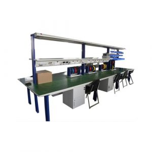
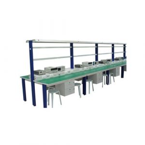
ZE1107 Electronics Workbench Educational Stand
ZE1107 Electronics Workbench Educational Stand. Jinan Should Shine Didactic Equipment Co., Ltd. is company specialized in manufacture and trading Engineering Educational Equipment,Technical Teaching Equipment, Vocational Training Equipment, Didactic Equipment for university,college, technical institution, polytechnics.Should Shine products has been exported to America,Asia,Europe, Africa, Australia.
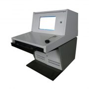
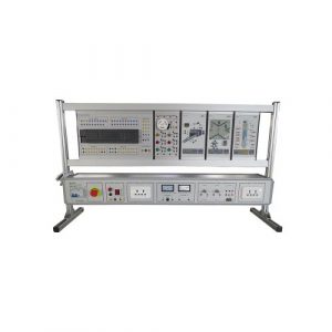
ZE3198 PLC Training Simulator Educational Equipment
ZE3198 PLC Training Simulator Educational Equipment for college,university, technical institute,vocational training schools.
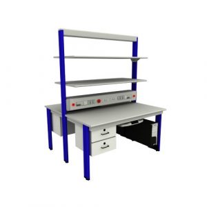
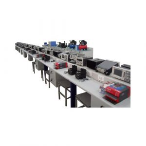
ZE1108 Technical Teaching Equipment Electronics Workbench
ZE1108 Technical Teaching Equipment Electronics Workbench. Jinan Should Shine Didactic Equipment Co., Ltd. is company specialized in manufacture and trading Engineering Educational Equipment,Technical Teaching Equipment, Vocational Training Equipment, Didactic Equipment for university,college, technical institution, polytechnics.Should Shine products has been exported to America,Asia,Europe, Africa, Australia.
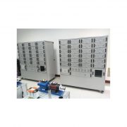
ZE1112 Vocational Training Equipment
ZE1112 Vocational Training Equipment. Jinan Should Shine Didactic Equipment Co., Ltd. is company specialized in manufacture and trading Engineering Educational Equipment,Technical Teaching Equipment, Vocational Training Equipment, Didactic Equipment for university,college, technical institution, polytechnics.Should Shine products has been exported to America,Asia,Europe, Africa, Australia.
ZE1105 Electronics Workbench Educational Training Equipment
ZE1105 Electronics Workbench Educational Training Equipment
Jinan Should Shine Didactic Equipment Co., Ltd. is company specialized in manufacture and trading Engineering Educational Equipment,Technical Teaching Equipment, Vocational Training Equipment, Didactic Equipment for university,college, technical institution, polytechnics.Should Shine products has been exported to America,Asia,Europe, Africa, Australia.
ZE1101 Electronics Workbench Technical Teaching Equipment
ZE1101 Electronics Workbench Technical Teaching Equipment. Jinan Should Shine Didactic Equipment Co., Ltd. is company specialized in manufacture and trading Engineering Educational Equipment,Technical Teaching Equipment, Vocational Training Equipment, Didactic Equipment for university,college, technical institution, polytechnics.Should Shine products has been exported to America,Asia,Europe, Africa, Australia.
ZE2101 Vocational Training Equipment
ZE2101 Vocational Training Equipment. Jinan Should Shine Didactic Equipment Co., Ltd. is company specialized in manufacture and trading Engineering Educational Equipment,Technical Teaching Equipment, Vocational Training Equipment, Didactic Equipment for university,college, technical institution, polytechnics.Should Shine products has been exported to America,Asia,Europe, Africa, Australia.
ZE1110 Teaching Equipment Digital Electronics Trainer
ZE1110 Teaching Equipment Digital Electronics Trainer
Jinan Should Shine Didactic Equipment Co., Ltd. is company specialized in manufacture and trading Engineering Educational Equipment,Technical Teaching Equipment, Vocational Training Equipment, Didactic Equipment for university,college, technical institution, polytechnics.Should Shine products has been exported to America,Asia,Europe, Africa, Australia.
ZE1111 Didactic Equipment
ZE1111 European Type Electronics Workbench Didactic Equipment. Jinan Should Shine Didactic Equipment Co., Ltd. is company specialized in manufacture and trading Engineering Educational Equipment,Technical Teaching Equipment, Vocational Training Equipment, Didactic Equipment for university,college, technical institution, polytechnics.Should Shine products has been exported to America,Asia,Europe, Africa, Australia.
ZE1109 Electronics Educational Equipment Teaching Equipment
ZE1109 Electronics Educational Equipment Teaching Equipment Jinan Should Shine Didactic Equipment Co., Ltd. is company specialized in manufacture and trading Engineering Educational Equipment,Technical Teaching Equipment, Vocational Training Equipment, Didactic Equipment for university,college, technical institution, polytechnics.Should Shine products has been exported to America,Asia,Europe, Africa, Australia.
-300x300.jpg)