- Description
- Inquiry
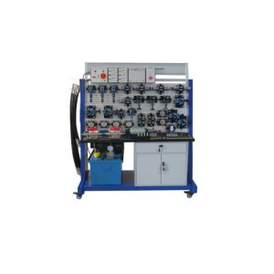
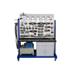
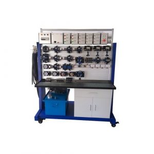
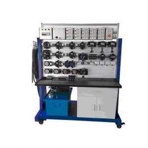
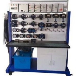
ZMH2109 Double Sides Electro Hydraulic Trainer Vocational Training Equipment Educational Equipment
3.1 Electrical control unit
The electrical control unit includes a total control switch hanging box, a DC power hanging box, a relay hanging box, a button hanging box and an emergency stop hanging box.
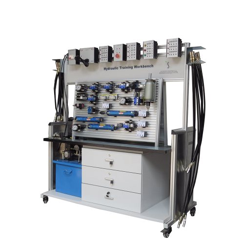
3.2 Training workbench
The training platform is composed of aluminum profiles and aluminum alloy substrates. The hydraulic station and cabinets are placed in the lower part. The inclined operation panel is ergonomic and easy to operate.
3.3 Power box
Single-phase three-wire power input, protected by insurance, with a main power switch. In case of emergency, the main power switch is turned off to stop the execution of the object.
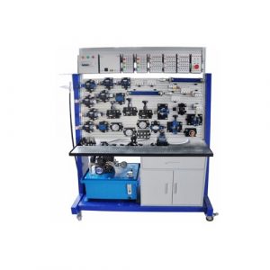
3.4 Hydraulic components
– 1x pediment of insertions of double sided electrical components
– 2x Fixed cabinet with 3 drawers
– 2x Rubber oil recovery tray
– 1x Cable guide
– 1x Hose support
Equipment set for the study of hydraulics and hydraulic electro
– 1x Hand operated 4/2 dispenser and spring reminder
– 1x Manually controlled 4/3 distributor, centre in Y
– 1x Manually controlled 4/3 distributor, closed centre
– 1x Non-return valve
– 1x Piloted non-return valve
– 1x Direct controlled pressure limiter
– 1x bidirectional flow strangler
– 1x unidirectional flow strangler
– 2x Dual effect cylinders 25mm piston diameter, 16 mm rod diameter and 200 mm stroke
– 1x Cylinder mounting kit
– 1x Hydraulic motor with 60 Nm torque drainage
– 1x Load mass of 15 kg with attachment adapted to the delivered cylinder assembled in a safety mesh
– 1x hydraulic membrane accumulator with locking diaphragm.
– 3x Manometer with quick connection and glycerin bath pressure range 0- 100 bar
– 2x T-Dispatcher with quick connection
– 1x Stop valve
– 2x 3 electric relay module (3NO-3NC contacts for each relay, 24 VDC reel);
– 1x Module of 3 electric push buttons
– 1x Module of 2 temporized relays (2NO-2NC contacts)
– 2x 4/2 monostable electric steering valve (24 VDC coil with excitation light)
– 1x Electric controlled centre 4/3 valve (24 VDC coil with excitation light
– 1x electronic pressure
– 2x Electronic proximity detector
Set of accessories
– 10x Flexible hose with quick couplings, 600 mm
– 6x Flexible hose with quick couplings, 1000 mm
– 4x Flexible hose with quick couplings, 1500 mm
– Set of 4 mm secure laboratory cables (red and blue) consisting of 80 minimum cables
– Power supply unit for mounting frame 220V AC – 24VDC/ 10A short-circuit protected.
Hydraulic unit
– Control with protective circuit breaker and integrated emergency stop
– 1 Single phase alternating current motor Nominal voltage: 230 V/50Hz
– Total rated engine power: 1 kW
– Coupled with 2 double pumps (gear or pallet pump)
– Flow rate of each pump: 3.5 l/min
– Pressure 50 bar
– Tank capacity 40 Liter with filter on return channel.
Delivered with French training documents with exercise and example paper and digital format on CD-ROM
– Manual of practical work in basic hydraulics;
– Manual of Practical Work in Hydraulic Electronics
3.5 Experiment list
(Note: The following experimental contents may not meet the experiment according to the component configuration of the device, for reference only!)
Experiment 1. Commutation circuit of manual reversing valve
Experiment 2. Commutation circuit of electromagnetic reversing valve
Experiment 3. Single stage pressure regulating circuit
Experiment 4. Single stage decompression circuit
Experiment 5. Secondary decompression circuit
Experiment 6. Pressure-retaining circuit with pressure relay
Experiment 7. Unloading circuit with “M” type directional control valve
Experiment 8. Unloading circuit with reversing valve
Experiment 9. Balance circuit with sequence valve
Experiment 10. Brake circuit with relief valve
Experiment 11. Secondary pressure circuit
Experiment 12. Oil passage throttle speed control loop
Experiment 13. Return circuit throttle control loop
Experiment 14. Parallel oil throttle throttling speed control loop
Experiment 15. Volume speed control loop
Experiment 16. Speed control valve parallel circuit
Experiment 17. Speed control valve series circuit
Experiment 18. Sequential action loop using the travel switch
Experiment 19. Buffer circuit with overflow valve
Experiment 20. Locking circuit with “M” type directional control valve
Related Products
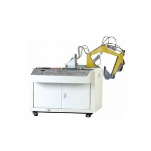
SSMT108 Transparent Hydraulic Excvavtor Trainer Teaching Equipment
SSMT108 Transparent Hydraulic Excvavtor Trainer Teaching Equipment. Jinan Should Shine Didactic Equipment Co., Ltd. is company specialized in manufacture and trading Engineering Educational Equipment,Technical Teaching Equipment,Vocational Training Equipment,Didactic Equipment for university,college,technical institution, polytechnics.Should Shine products has been exported to America,Asia,Europe,Africa, Australia.
Hydraulic Training Workbench Didactic Equipment Hydraulic Training Workbench
ZMH1100 Hydraulic Training Workbench Didactic Equipment Hydraulic Training Workbench for college, vocational training center, university.
Electro-hydraulic Workbench for Training (Double Sided) Vocational Training Equipment Hydraulic Training Equipment
SR6116 Electro-hydraulic Workbench for Training (Double Sided) Vocational Training Equipment Hydraulic Training Equipment for college, vocational training center, university.
Basic Level: Mobile Hydraulics – Working Hydraulics Educational Equipment Hydraulic Training Equipment
AH203 Basic Level: Mobile Hydraulics – Working Hydraulics Educational Equipment Hydraulic Training Equipment for college, vocational training center, university.
ZMH1107T Transparent Electro Hydraulic Trainer Educational Training Equipment
ZMH1107T Transparent Electro Hydraulic Trainer Educational Training Equipment. Jinan Should Shine Didactic Equipment Co., Ltd. is company specialized in manufacture and trading Engineering Educational Equipment,Technical Teaching Equipment,Vocational Training Equipment,Didactic Equipment for university,college,technical institution, polytechnics.Should Shine products has been exported to America,Asia,Europe,Africa, Australia.
ZMH1107 Electro Hydraulic Trainer Vocational Training Equipment
ZMH1107 Electro Hydraulic Trainer Vocational Training Equipment. Jinan Should Shine Didactic Equipment Co., Ltd. is company specialized in manufacture and trading Engineering Educational Equipment,Technical Teaching Equipment,Vocational Training Equipment,Didactic Equipment for university,college,technical institution, polytechnics.Should Shine products has been exported to America,Asia,Europe,Africa, Australia.
ZMH1108 PLC Electro Hydraulic Trainer Teaching Equipment
ZMH1108 PLC Electro Hydraulic Trainer Teaching Equipment. Jinan Should Shine Didactic Equipment Co., Ltd. is company specialized in manufacture and trading Engineering Educational Equipment,Technical Teaching Equipment,Vocational Training Equipment,Didactic Equipment for university,college,technical institution, polytechnics.Should Shine products has been exported to America,Asia,Europe,Africa, Australia.
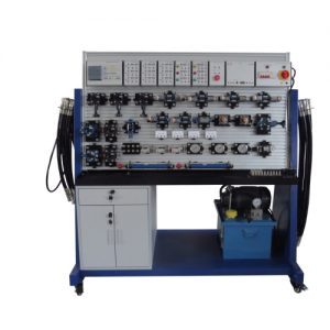
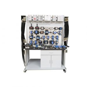
ZMH2107 Double Sides Proportional Hydraulic Trainer Hydraulic Bench
ZMH2107 Double Sides Proportional Hydraulic Trainer Hydraulic Bench
I.Introduction
I‘s suitable for schools, engineer training centers, factory training department etc.
Through this trainer, students can master hydraulic components structure, hydraulic circuit control theory, hydraulic circuit design, and hand on ability for hydraulic trainer.
This trainer is flexible and students can design their own hydraulic circuit.
- II. Technical parameter
(1) DC power: input AC 380V,50Hz Output: DC 24V/3A
(2)Wheel: 4, 2 lockable with brake, 2 not lockable
(3) Hydraulic station:
nominal volume: 35L
rated output hydraulic pressure is 16MPa,
pump type: gear pump
(4) Slot space:25mm
(5) Panel material: aluminum
(6) Workbench type: double sides four work stations for 4 students
(7) Hydraulic station with hydraulic oil
(8) Whole equipment dimension:1600mm(L)×850mm(W)×1700mm(H)
(9)Aluminum panel dimension: 1200(L)×750(W)
(10)Cabinet: 2
III. Experiment that can be finished
- 1. Direction control circuit
(1)Hand operated direction valve direction change circuit
(2)Solenoid directional valve direction change valve
- 2. Pressure control circuit
(1)Single grade pressure adjust circuit
(2)Secondary pressure adjust
(3)Single grade pressure decrease circuit
(4)Secondary reduce pressure circuit
(5)Use “M” direction change valve lief circuit
( 6)Use selector valve lief circuit
(7)Use overflow valve lief circuit
(8)pilot operated check valve protect voltage
- 3. Speed adjust circuit
(1)Oil inlet throttling governing
(2)Back oil circuit throttling governing
(3)By pass circuit throttling governing
(4)Speed adjust valve speed synchronizing circuit
(5)Speed adjust valve parallel circuit
(6)Speed adjust series circuit
- 5. Use sequence valve sequent circuit
- 6. Use stroke switch control sequent circuit
- 7. Use pressure relay control sequent circuit
- 8. Use pilot operated check valve single direction lock close circuit
- 9. Use pilot operated check valve two directional close circuit
- 10. Use “O” type directional change valve close circuit
- 11. Relay control hydraulic basic circuit
- Hydraulic component capacity measure experiment
Proportional Hydraulic Training Workbench (Single Side) Educational Equipment Hydraulic Training Equipment
ZMH1115 Proportional hydraulic training workbench (single side) educational equipment hydraulic training equipment for college, vocational training center, university.
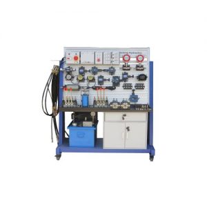
ZMH2115 Proportional Hydraulic Trainer Educational Equipment
ZMH2115 Proportional Hydraulic Trainer Educational Equipment. Jinan Should Shine Didactic Equipment Co., Ltd. is company specialized in manufacture and trading Engineering Educational Equipment,Technical Teaching Equipment,Vocational Training Equipment,Didactic Equipment for university,college,technical institution, polytechnics.Should Shine products has been exported to America,Asia,Europe,Africa, Australia.